

Contact us for a quote and free process design
know what you are expecting from mining project and we are making it happen with
unrivalled products and services.
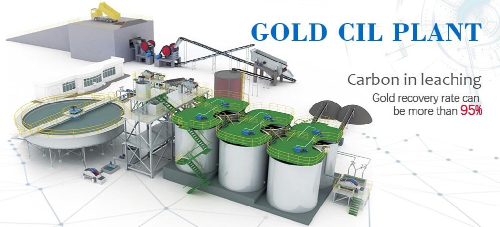
Do you know the gold CIL (CIP) Processing plant ?Gold CIP (CIP) is a widely used method for extracting gold from ore. It involves using activated carbon to adsorb gold from a cyanide solution, followed by elution and regeneration of the carbon for reuse.Gold CIP (CIP) is ideal for processing gold-co
Do you know the gold CIP Processing plant ?
Gold CIP is a widely used method for extracting gold from ore. It involves using activated carbon to adsorb gold from a cyanide solution, followed by elution and regeneration of the carbon for reuse.
Gold CIP is ideal for processing gold-containing oxidized ore with a high slime content. Terbaik machinery is a leading supplier that offers custom gold CIP processing plants and equipment to address these challenges efficiently.
The Gold CIP (Carbon-in-Pulp) Process is a gold extraction technique where gold is leached from ore using a cyanide solution, and then adsorbed onto activated carbon directly from the ore pulp. This is a key difference from the CIL (Carbon-in-Leach) process. In CIL, leaching and adsorption occur simultaneously in the same tanks. In CIP, gold leaching typically happens in dedicated tanks first, followed by adsorption in separate tanks where activated carbon is introduced. This staged approach allows for optimizing leaching conditions independently of adsorption conditions. Compared to Merrill-Crowe (zinc precipitation), CIP/CIL is generally more effective for lower-grade ores and ores with significant silver or copper, as carbon is more selective for gold.
Before you choosing the gold CIP Plant you should consider following questions ?
A. You should know the grade of your gold ?
Selecting or customizing the most suitable Gold CIP Process solution for your gold project depends on various factors, including project scale, ore characteristics, and
economic objectives.
Ore Type: Is it a straightforward oxide ore, or a complex refractory gold ore or preg-robbing ore? This dictates the need for pre-treatment steps and whether CIP
is more appropriate. For high preg-robbing ores, CIP is generally preferred.
Gold Grade and Tonnage: For very small, high-grade deposits, simpler methods might be considered. CIPPis well-suited for large, low-to-medium grade deposits.
The CIL process for gold ore is suitable for the beneficiation of small-to-medium-sized gold mines with low grades (1.5–9%), as well as for gold deposits containing significant
associated silver and copper. Compared to the Carbon-in-Pulp (CIP) method and traditional beneficiation techniques, the utilization of this process yields significant
improvements in economic efficiency.
B What is the typical gold recovery in a Gold CIP Process?
Typical gold recovery can range from 85% to over 95%, depending on ore characteristics (liberation, refractoriness) and process optimization. For highly refractory ores, recovery
might be lower without pre-treatment.
C How much activated carbon is used in a Gold CIP plant?
The inventory of activated carbon in the adsorption circuit is typically designed to be 20 to 50 grams of carbon per liter of pulp in each tank. Daily carbon consumption (
make-up for losses and regeneration inefficiencies) is much lower.
D Is the Gold CIP Process environmentally friendly?
Like any gold cyanidation process, it uses toxic cyanide. However, with proper engineering design, strict operational controls, and effective tailings detoxification systems,
the environmental impact can be managed to meet regulatory standards.
E What’s the difference between K-value and R-value for activated carbon?
K-value (equilibrium loading capacity) indicates how much gold the carbon can adsorb at equilibrium. R-value (adsorption rate) indicates how fast the carbon adsorbs gold.
Both are important for efficient gold adsorption by activated carbon.
2. Preparation Prior to Cyanidation
When employing the Carbon-in-Pulp (CIP) gold recovery process, prior to cyanide leaching, in addition to ore crushing and grinding, the removal of debris, pulp thickening,
and the addition of scale inhibitors are also essential steps.
2.1 Debris Removal Operations
Wood chips, grass roots, and other miscellaneous debris present in the pulp can easily cause blockages in pipelines and screens; furthermore, wood chips can adsorb gold,
making their removal prior to leaching imperative.
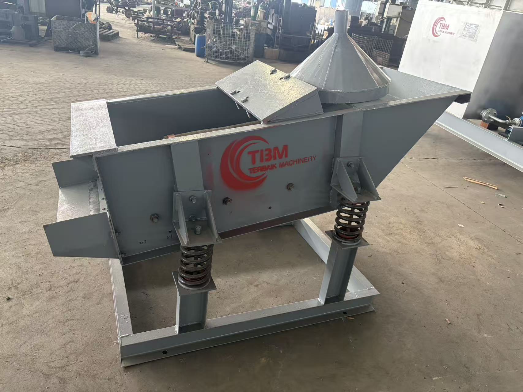
Typically, the grinding circuit is designed to incorporate two debris removal stages, positioned at the overflow points of the primary and secondary grinding and classification
circuits, respectively. Medium-frequency linear
vibrating screens are the most commonly used equipment for debris removal; however, spiral screens and trommel screens are also occasionally utilized during the initial removal
stage. Regarding the mesh size of the debris screens,
the requirement is to keep the aperture as small as possible while ensuring that the screen surface does not experience overflow (i.e., loss of pulp).
2.2 Pre-Leach Thickening
In typical CIP gold recovery processes, the fineness of the overflow from the grinding and classification circuit generally falls within the range of 85–95% passing -200 mesh.
When processing flotation concentrates,
the fineness of the grinding and classification overflow is even finer, reaching over 99% passing -300 mesh. The solids concentration of this overflow is typically between
18% and 22%, which is unsuitable for direct leaching; therefore,
the pulp must undergo thickening.
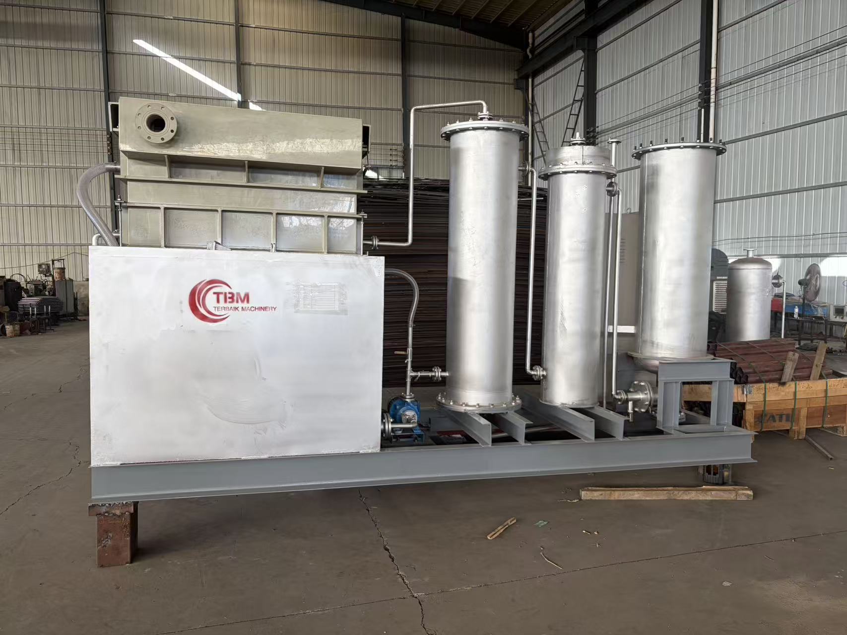
High-efficiency thickeners—characterized by their small footprint and high operational efficiency—are the equipment of choice for this thickening process.
2.3 Addition of Scale Inhibitors
To minimize scale formation on the surface of the activated carbon, as well as on screens and other equipment components, a specific quantity of scale inhibitor
may be added to the pulp prior to the leaching process.
3.Leaching and Adsorption
A defining characteristic of the Carbon-in-Pulp (CIP) method is that the leaching and adsorption of gold occur simultaneously. The leaching circuit typically consists of 6 to 10 stages
(tanks). Since sodium cyanide is initially
introduced into the first tank, the extent of gold leaching in this specific tank is relatively low; consequently, most CIP plants designate the first tank as a "pre-leach" tank,
while the subsequent tanks serve as the
primary "leaching and adsorption" tanks. Each leaching-adsorption tank is equipped with a carbon-retention screen to separate the carbon from the ore slurry. The slurry
flows in a forward direction, while the activated carbon
flows in a counter-current direction; specifically, fresh activated carbon is introduced into the final leaching-adsorption tank, while gold-loaded carbon is discharged from
the first tank. After screening and rinsing, the loaded
carbon is transferred to the desorption and electrowinning section. Following this adsorption process, the gold grade in the residual slurry solution typically ranges from
0.01 to 0.03 g/m³.
3.1 Cyanide Leaching
During the leaching process, cyanide is utilized to extract gold and silver from the ore, forming gold and silver cyanide complexes. Lime is added to maintain an elevated
pH level, thereby preventing the formation of toxic
hydrogen cyanide gas. In highly automated carbon-in-leach (CIL) plants, hydrogen cyanide gas detectors are installed throughout the leaching and adsorption areas.
Key Leaching Parameters
Fineness of Milled Product: 85–95% passing -200 mesh
Slurry Concentration: 40–45%
Cyanide Concentration: Not less than 0.015%
Slurry pH: 10–11
Aeration Rate: 0.002–0.003 m³/min per m³ of slurry
Number of Leaching Stages: 6–10
Convenient transportation, crawler walking, no damage to the road, equipped with multi-functional accessories, Drived by oil and electricity.
The whole crushing plant adopts all-wheel drive to realize rotating direction in place, with perfect protection function, especially suitable for narrow and complex site.
The crawler crushing plant could be optional for jaw crusher, impatct crusher, cone crusher, VSI crusher etc.
It can work uphill to meet the crushing requirements of mining, hydropower station, coal mine and other projects.
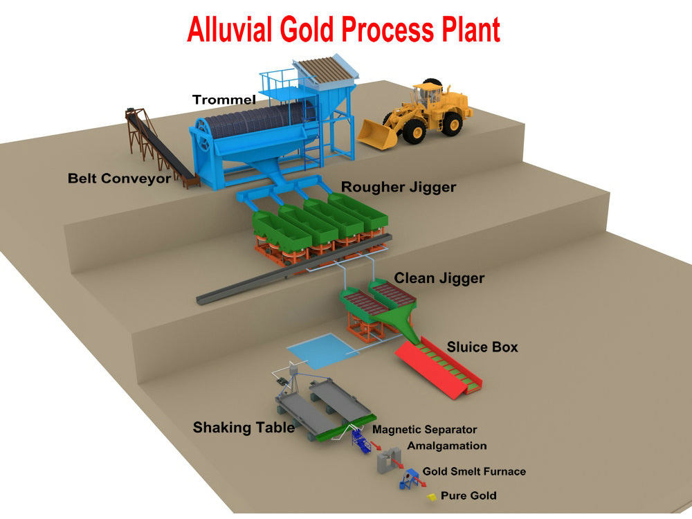
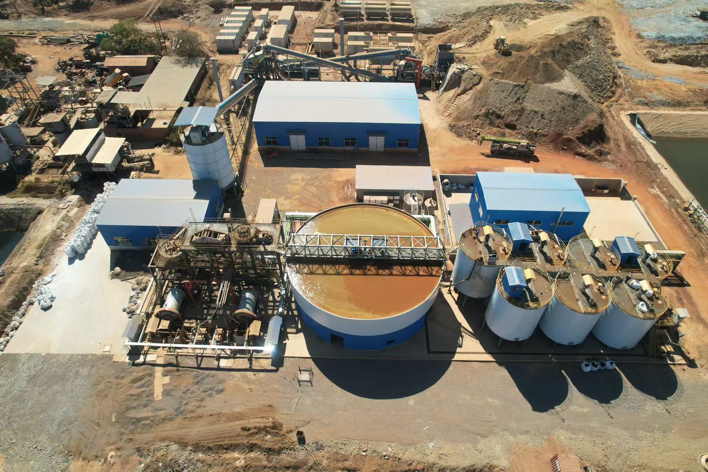
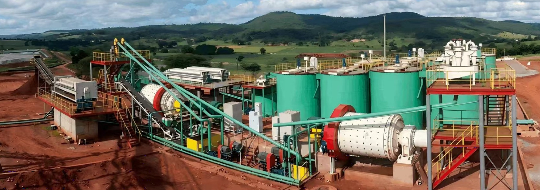
A complete Gold CIP Process flow involves several core steps, each with a specific objective, from ore preparation to producing gold doré.
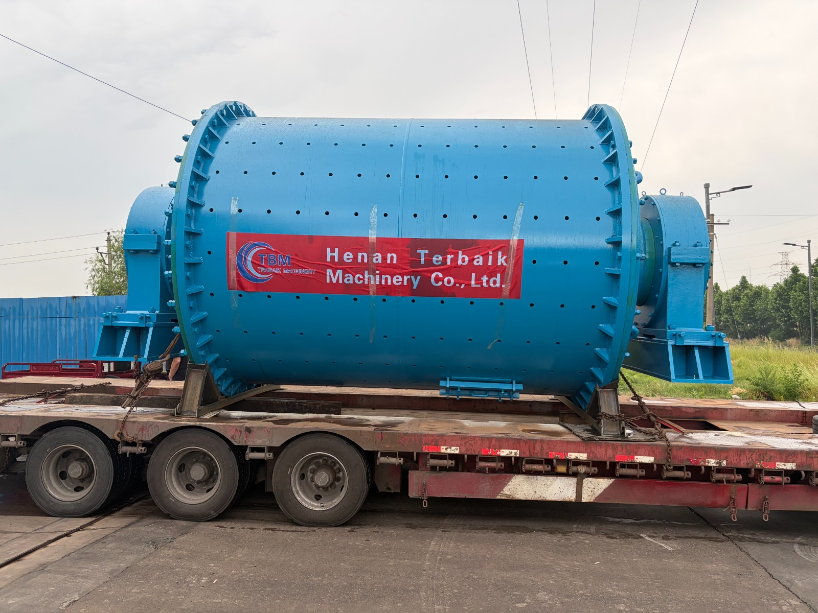
Comminution: Ore is first crushed using Cone Crushers, then ground in Ball Mills to a fine pulp. The goal is to liberate the gold particles for effective gold leaching.
Pre-treatment (if needed): For refractory gold ore or preg-robbing ore, steps like pre-aeration, oxidation, or flotation to remove carbon might be included.
Leaching: The ground ore pulp is mixed with a dilute sodium cyanide solution and lime (for pH control) in large, agitated Mixer tanks (leach tanks). Gold dissolves to form a gold-cyanide complex. Sufficient retention time and oxygen are critical.
Adsorption: The leached pulp flows through a series of adsorption tanks. Activated carbon granules are added counter-currently to the pulp flow. The gold-cyanide complex adsorbs onto the carbon. Interstage screens prevent carbon from moving downstream with the pulp.
Carbon Elution (Desorption): Loaded carbon is removed from the first adsorption tank and transferred to an elution column. Here, a hot caustic-cyanide solution (or other eluant) strips the gold from the carbon. This step is crucial for gold recovery.
Electrowinning: The gold-rich eluate solution flows to electrowinning cells, where gold is deposited onto cathodes (steel wool).
Carbon Regeneration: The barren carbon from elution is reactivated by thermal activated carbon regeneration in a kiln to restore its adsorptive properties before being returned to the adsorption circuit.
Smelting: The gold sludge from the cathodes is dried, mixed with fluxes, and smelted to produce gold doré bars.
A critical insight is the “oxygen starvation” in leaching. Even with high air input, if pulp viscosity is high or oxygen-consuming minerals are present, the actual dissolved oxygen at the mineral surface can be a limiting factor, not just the exhaust gas oxygen content.
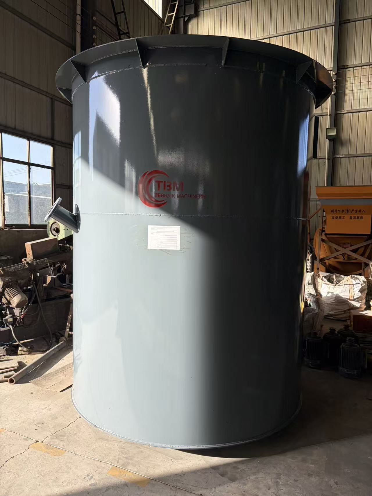
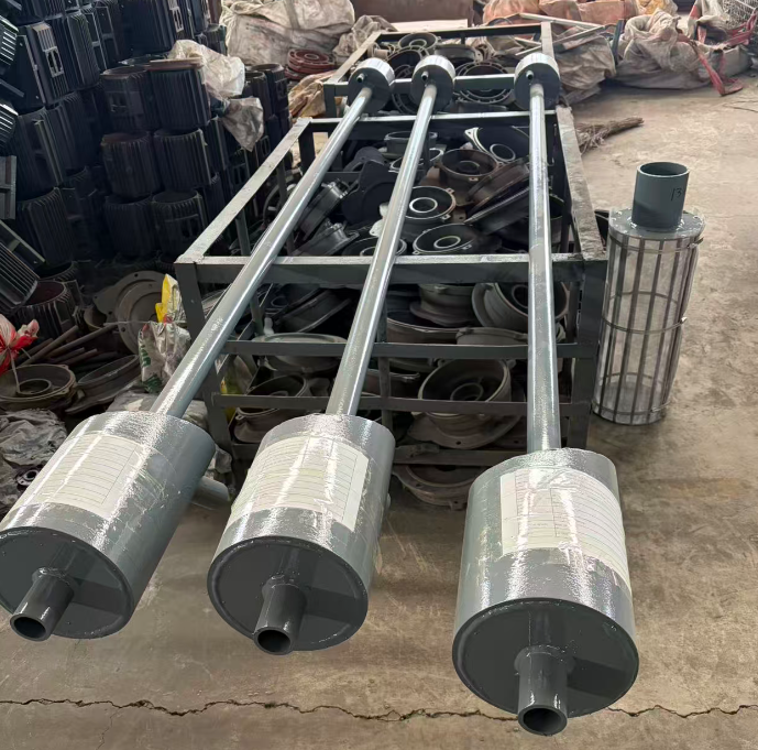
The reaction between gold, silver, and cyanide requires the participation of oxygen. Theoretically, the oxygen consumption per gram of gold is 0.04 g; however,
in actual production, oxygen consumption is significantly higher because ores often contain various metal sulfides, which also consume oxygen during their reactions
with cyanide. Consequently, actual production processes typically introduce medium-pressure air (at 100 kPa) through the hollow shafts of the agitators. Airflow is generally
controlled and measured using rotameters.
In recent years, driven by the pursuit of two key technical-economic objectives—intensifying the leaching process and reducing cyanide consumption—the oxygen-enriched
leaching process for gold recovery (CIP) has emerged. The primary advantages of utilizing CIP include:
(1) Accelerating leaching kinetics and reducing leaching time; in some instances, it also increases the leaching recovery rates for gold and silver;
(2) Lowering cyanide consumption;
(3) Achieving superior leaching results for finely ground ores compared to agitation using standard air injection;
(4) Enabling the effective leaching of ores containing minerals with high oxygen-consuming potential.
At a specific gold mine in Hebei Province, the agitation method was switched from compressed air to oxygen-enriched leaching. While retaining the original equipment
configuration, a single oxygen generation unit was installed to replace the existing air compressor. As a result, the leaching time was reduced from the original 36–42 hours
to approximately 20 hours; furthermore, the gold leaching recovery rate increased by 0.89%, and cyanide consumption was reduced by 0.27 kg per ton of ore. Due to the
reduction in leaching time, the production capacity of the original set of leaching equipment rose from 300 tons per day to 643 tons per day, generating significant economic
benefits.
Hydrogen peroxide (H₂O₂) can also be used as a substitute for compressed air to achieve the objectives of oxygen-enriched leaching; however, the specific efficacy of this
approach must be determined through laboratory testing and pilot-scale production trials.
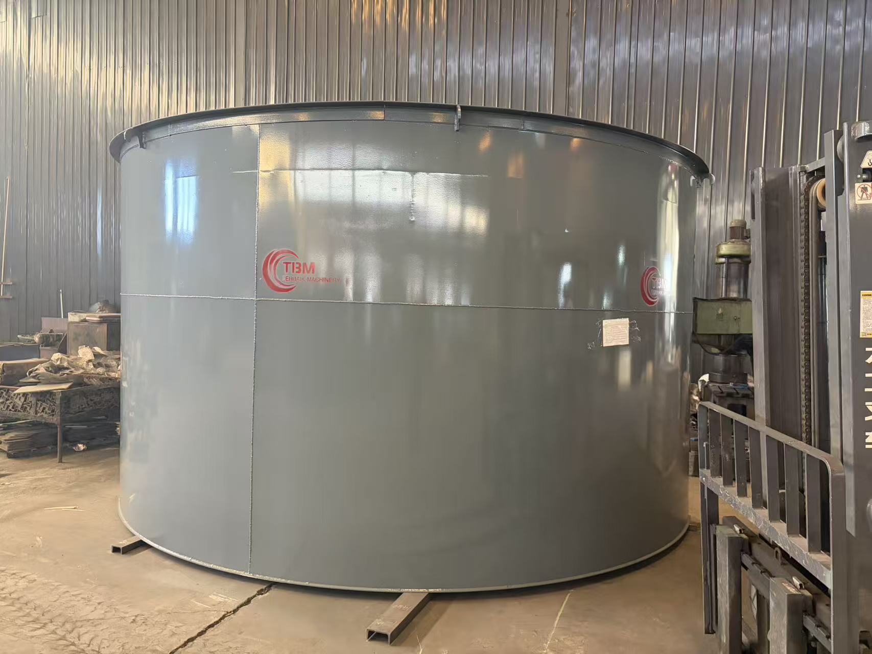
3.2 Activated Carbon Adsorption
The most commonly used activated carbon is coconut shell activated carbon, which possesses excellent adsorption properties and high abrasion resistance. Each adsorption
tank must be equipped with carbon retention screens; typically, 24-mesh 304 stainless steel screens are selected for this purpose.
Carbon retention screens are predominantly cylindrical or V-shaped in design, although vibrating screens or other configurations are also occasionally employed. The main
factors influencing activated carbon adsorption include:
3.2.1 Influence of Activated Carbon Properties
This includes the influence of the carbon's adsorption capacity, mechanical strength, and particle size.
3.2.2 Influence of Pulp Properties
This primarily includes the influence of coarse sand and wood chips; pulp concentration and viscosity; organic matter content within the pulp; pulp pH value; and the presence
of carbonaceous ores.
3.2.3 Influence of Operating Parameters
Operating parameters mainly include aeration rate, aeration method, cyanide concentration, and the carbon inventory maintained within the process circuit.
3.3 Monitoring and Control
During the production process, laboratory technicians are required to monitor parameters such as pulp concentration, pH value, cyanide ion concentration, and the density
of the carbon bed. Typically, these measurements are taken once every two hours. In beneficiation plants with a high degree of automation, online monitoring systems can
be utilized to automatically adjust pulp concentration, pH, and cyanide levels. Operators are required to conduct continuous, on-the-spot inspections of aeration rates,
carbon-retention screens, and the surface levels of the pulp tanks.
4.Desorption and Electrowinning of Gold-Loaded Carbon
The gold-loaded carbon and accompanying pulp are conveyed—typically via a carbon-lifting pump or an air-lift pump—to a carbon separation screen (usually a linear
vibrating screen). On the screen, the carbon is rinsed with fresh water to separate it from the pulp; the gold-loaded carbon then proceeds to a carbon storage tank, while
the pulp and rinse water flow into the first stage of the adsorption tanks.
Several methods exist for the desorption of gold-loaded carbon. In my country, the most commonly adopted methods are the Zadra process, the high-temperature and
high-pressure desorption method, and integrated pressure desorption systems.
4.1 The Zadra Process
The Zadra process employs a solution containing 0.1% sodium cyanide and 1% sodium hydroxide as the desorption eluent. The process operates under atmospheric pressure
at temperatures ranging from 85°C to 95°C, with a desorption duration of 24 to 72 hours. While this method is simple to implement and entails low capital investment and
operating costs, it is time-consuming and involves a relatively poor working environment.
4.2 High-Temperature and High-Pressure Desorption Method
In the high-temperature and high-pressure desorption method, the desorption eluent consists of an aqueous solution containing 0.1% sodium cyanide and 1% sodium hydroxide.
The process is conducted at temperatures between 150°C and 170°C and a pressure of 0.35 MPa; under these conditions, the required process parameters can be achieved
within a desorption period of just 4 to 6 hours. This method significantly reduces reagent consumption, features a rapid desorption rate, and allows for a short carbon cycle;
however, prior to the discharge of the rich desorption solution, it must be cooled to prevent boiling and splashing.
4.3 Integrated Pressure Desorption System
The basic process flow of the integrated pressure desorption system is similar to that of the high-temperature, high-pressure desorption method. However, since the
electrowinning operation is also conducted within the pressurized system, issues such as boiling and splashing do not occur. Furthermore, the solution requires no cooling
prior to entering the electrowinning stage, and a 5% sodium hydroxide solution suffices as the desorption agent. The operating parameters for this method are as follows:
desorption temperature of 150°C, desorption pressure of 0.5 MPa, desorption time of approximately 6 hours, electrowinning voltage of 2.5–3.0 V, and electrowinning
current of 250 A. This method is the most widely adopted in practice.
5.Carbon Regeneration
After undergoing adsorption and desorption cycles, activated carbon requires regeneration to restore its optimal adsorption properties. Regeneration processes are generally
categorized into acid washing and thermal regeneration. Acid washing typically involves soaking the carbon in a dilute 5% nitric acid solution. Production practices—
both domestically and internationally—indicate that acid washing removes only a portion of the inorganic substances adsorbed onto the carbon; while it effectively
restores the activated carbon's iodine and carbon tetrachloride values and reduces its inorganic ash content, it does not fully restore the carbon's adsorption capacity or
adsorption rate. Consequently, after multiple acid washing cycles, thermal regeneration becomes necessary. The thermal regeneration process comprises four distinct steps:
drying, carbonization, removal of carbonaceous residues, and cooling. Following thermal regeneration, the carbon's adsorption capacity and adsorption rate are fully restored,
and its adsorption activity can approach or even reach the level of fresh carbon. 6
Main Equipment of the Carbon-in-Pulp (CIP) Plant
6.1 Pre-leaching Preparation Equipment
Includes crushers, belt conveyors, vibrating screens, ball mills, classifiers, trash screens, thickeners, slurry pumps, etc.
6.2 Leaching and Adsorption Equipment
Includes leaching tanks, adsorption tanks, carbon lifting equipment, carbon separation screens, safety screens, etc.
6.3 Desorption and Electrowinning Equipment
Conventional Zadra method desorption and electrowinning equipment includes: desorption columns, electric heaters, electrowinning cells, filters, heat exchangers,
corrosion-resistant pumps, etc.; integrated pressure desorption systems include desorption columns, electric heaters, electrowinning cells, filters, corrosion-resistant pumps, etc.
*The output will vary according to different materials, feed particle size and other factors
 +86-19139706301
 +86-19139706301